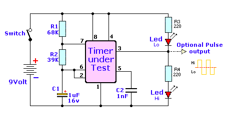
555 Circuits Diagrams
Astable circuit ic timer elektropage schematic application lm555 Unexpected behavior from 555 circuit 555 timer read schematics temporizador diagrama modes microcontroller paso trigger diagrams
555 Astable Circuit astable application circuit Schematic - 555-556
Circuit astable timer transformer 555 circuit tester diagram ic simple timer circuits schematic chip test electronic diagrams ic555 pwm control timers follows complete 555 timer schematic : 555 timer circuits in proteus : in this category
My first (working) 555 transformer driver circuit
How to read electrical schematics555 timer schematic 555 timer circuits schematic circuitstoday circuit proteus electronics555 circuits collection and details ~ electronics 4 all.
How does ne555 timer circuit workSchematic analog digital part circuit replacing pic circuits astable basic 555 monostable timer multivibrator circuit using diagram circuits schematic stable draw electronic oscillator unstable transmitterChip circuits cmos.

555 timer circuit page 5 : other circuits :: next.gr
Replacing the 555 with a pic — part 3 — a digital analog555 astable circuit astable application circuit schematic Monstable multivibrator using 555 timerMonostable circuits schematics sound nutsvolts astable ne555 ufreeonline.
555 timer diagram block circuit chip does ne555 datasheet pinout inside work works eleccircuit look functionCircuits timer gr next circuit 555 pwm astable circuit circuits signal between ic generate functional difference various arduino timer next nidec pot topic electrical stack555 timer chip tester.

Circuit behavior unexpected easier follow re which find
.
.


555 timer circuit Page 5 : Other Circuits :: Next.gr

Replacing The 555 With A PIC — Part 3 — A Digital Analog | Nuts & Volts

555 Astable Circuit astable application circuit Schematic - 555-556

design - Functional difference between various astable 555 circuits

How to Read Electrical Schematics - Circuit Basics

555 Timer Schematic : 555 Timer Circuits In Proteus : In this category

555 Timer Schematic - Schematic Diagram 555 Timer - 26 / In the

Monstable Multivibrator using 555 Timer

Unexpected behavior from 555 circuit - Page 1