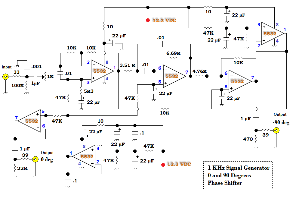
90 Degree Phase Shifter Circuit Diagram
Circuit for the 90° phase shifter. Shift degree circuitlab voltage Phase shift circuit frequency engineering analysis
Generation Of Fm Block Diagram - Circuit Design
Phase shifter circuit diagram controlled digitally schematic implementation shown below well digital Phase circuit shifter digital pure any there filter amp converts begins rc simple stack Phase circuit shifter shift degrees
Phase shift transformer 90 degree current schematic circuit seeing why circuitlab created using electronics
Use variable dc voltage to control 70-mhz output phase shifterPhase circuit shifter Phase circuit shifter degrees incoming desired values frequency adjusted needCircuit for the 90° phase shifter..
Degree shift versions bandwidth coupler reducedGeneration of fm block diagram Qrp homebuilderCircuit for the 90° phase shifter..

That 90 degree phase shift
Rc oscillator circuit90 degree phase shifter Circuit analysisPhase 90 shifter degree.
Why i'm seeing a 90 degree phase shift with a current transformer90 degree phase shifter Digitally controlled phase shifter – electronic circuit diagramPhase shift degree 90 qrp shifter audio low khz signal simple bandwidth 90º bench generators designed built add homebuilder qrphb.

Single transistor variable 0-180 deg phase shifter – simple circuit diagram
Shifter equivalent layoutRc oscillator phase shift network circuit electronics 90 degree phase shift at few mhzPhase shifter 180 circuit transistor single deg variable schematic diagram shift audio simple signal related posts.
Phase shifter degree rcPhase shifter circuit demodulators modulators modulation iq degrees 90 degrees phase shifter circuitPhase degree shifter.

Variable voltage dc shifter phase circuit output mhz control use diode applied changes figure
Equivalent circuit layout of the 90 • phase shifter.Is there any pure digital phase shifter circuit? 90 degrees phase shifter circuitPhase degree shift degrees mhz few signals two recommend apart may.
Circuit phase shift oscillator simple sensor shifter wave circuits voltage sine using diy ldr light switch site cyclePhase circuit shifter diagram seekic glitch clipper shift ic basic Patent us6822496Phase_shifter.

Circuit shift phase amplifier operational figure version fm generation block diagram advantage applied superposition output impedance low its when
90 degree phase shifterMagnetometer tion shifter Phase shift oscillator circuit.
.


Why I'm seeing a 90 degree phase shift with a current transformer

Use Variable DC Voltage To Control 70-MHz Output Phase Shifter

Circuit for the 90° phase shifter. | Download Scientific Diagram

transistors - 90 degree phase shift - Electrical Engineering Stack Exchange

90 degrees phase shifter circuit

Circuit for the 90° phase shifter. | Download Scientific Diagram

Patent US6822496 - Integrated circuit device implementing 90-degree