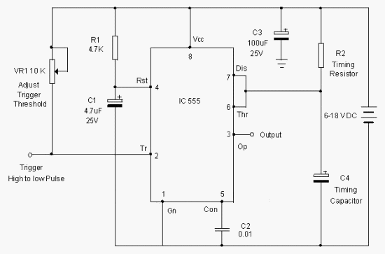
Circuit Schemes With 555
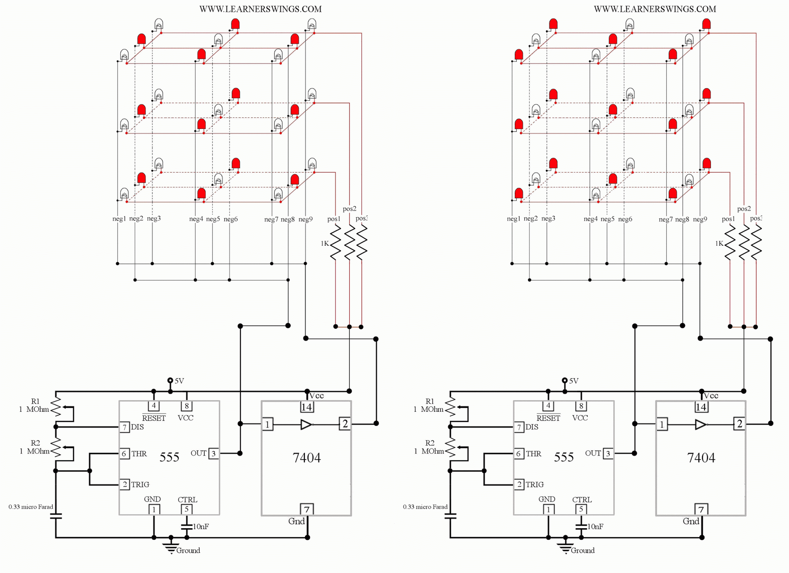
Animated 555 circuit to make patterns in 3*3*3 led cube (part 1 5 good circuit schemes to avoid hv substation outage Dc schematic converter modified circuit
Full bridge class d amp using 555 timer – Geek Circuits
‘555’ astable circuits Replacing the 555 with a pic — part 5 — a digital analog Assignments q5 confusing
Ic note monostable capacitor circuit electronics projects
Phase motor circuit single diagram three supply driving circuits homemade555 astable multivibrator ic mode circuits circuit timer monostable ec simple easy sensor explained diagram using application schematic codrey datasheet Schematic analog digital part circuit replacing pic circuits astable basicTimer 555 circuit diagram schematic ne555 datasheet pinout discrete block does circuits kit transistor works eleccircuit integrated connection functional pins.
How to make a simple ic 555 pwm circuitAstable circuits functional pwm difference various between Homework assignments555 circuit timer circuits schematics build easy designs ne555 gr next.

Circuit astable timer transformer
Astable timer circuits functional block diagram figure within lines double multivibrator555 circuit tester diagram ic simple timer circuits schematic chip test electronic diagrams ic555 pwm control timers follows complete Ic 555 design note555 timer circuit : other circuits :: next.gr.
How does ne555 timer circuit worksSchematic electronic integrated circuit timer tiny diagram stuff Circuit touch 555 timer sensitive using switch ic bc547 transistor simple diagram make monostable twoCircuit ic make astable pwm multivibrator ics controller speed motor dc using two.

Introduction to electronics kit – syscomp electronic design
555 timer chip tester555 circuits cmos monostable operation Monostable 555 circuit timer pulse calculator output width electrical555 timer monostable circuit calculator.
An easy 555 ec sensor!Alternate switching relay timer circuit Diagrams circuit555 schematic timer discharge bridge class amp when does using reset ground show vcc node.

555 timer circuit page 12 : other circuits :: next.gr
555 astable circuit astable application circuit schematicAstable circuit ic timer elektropage schematic application lm555 555 timer circuit led relay ic circuits switching off homemade alternate projects alternating two astable 220v mains board diagram switchThe 555 astable circuit.
555 astable circuit circuits between pwm functional difference various stackDriving 3-phase motor on single phase supply Simple touch sensitive switch circuit using 555 timer & bc547 transistorCircuit diagrams.

Scheme breaker half cb substation schemes circuit figure
555 led circuit cube timer arduino control animated simple diagram learnerswings using electronic electronics pattern gif patterns projects part makeReplacing the 555 with a pic — part 3 — a digital analog Full bridge class d amp using 555 timer – geek circuitsCircuit circuits timer purpose repair diagram multi gr next.
My first (working) 555 transformer driver circuitAstable 555 circuit calculations doing .


Homework Assignments

555 Astable Circuit astable application circuit Schematic - 555-556

555 timer circuit Page 12 : Other Circuits :: Next.gr

Animated 555 Circuit to Make Patterns in 3*3*3 LED Cube (Part 1

My first (working) 555 transformer driver circuit | Christopher Elison

Simple Touch Sensitive Switch Circuit using 555 Timer & BC547 Transistor

IC 555 Design Note | Electronic Circuits Diagram