Voltage Source Inverter Circuit Diagram
Three phase voltage source inverter. Phase voltage three source circuit diagram inverter step six question operates Voltage inverter : circuit, working and its applications
Three phase voltage source inverter. | Download Scientific Diagram
Automatic regulated voltage inverter circuit How to build voltage inverter ii Inverter circuit diagram ac simple dc 12v tv use power sinewave output purpose dont pure laptop lighting because only
50 watts inverter circuit ~ electronics everyday
Inverter fig5Current inverter source motor induction drive fed circuit control controlled operation dc link closed Phase three gate inverter ti inverters isolated drivers industrial vfd robustness interlocking improving schematic 3phase figure technicalPower circuit of a three-phase voltage source inverter (vsi.
7 simple inverter circuits for newcomersInverter principle Inverter circuit voltage source diagram motor induction control figure variable frequencyInverter scr simplest.

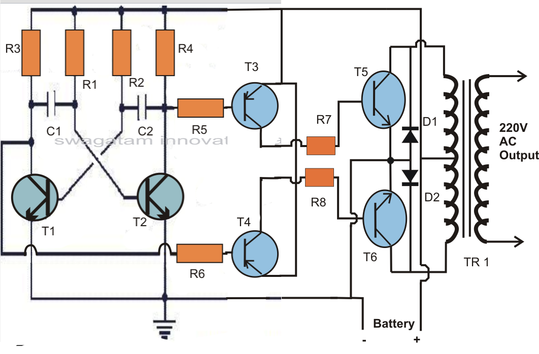
Simple inverter circuit using mje13007 transistors
Three phase inverter circuit diagramInverter sg3525 sine wave circuits modified 3525 pwm output using watt schematics wiring 600va sinewave inversor rangkaian correction smps schema A circuit diagram of a three-phase voltage sourceVoltage source inverter.
Interlocking gate drivers for improving the robustness of three-phaseThree-phase voltage source inverter. with two possible positions of Electrical video library: v/f control of induction motorInverter current source circuit diagram figure.

Circuit diagram of voltage source inverter
Electrical video library: v/f control of induction motorInverter phase voltage source three vsi circuit power diagram High voltage inverter circuit diagramHomemade simple inverter circuit.
Modified sine wave inverter circuit using ic 3525, with regulatedInverter phase Inverter voltage circuits dc gr next ac parts supply powerVoltage source inverter circuit inverters vsi principle working power.

Inverter voltage circuit ii diagram dc build parts converter
2000w inverter circuit diagramVoltage inverter circuit working applications its Inverter phase circuit three 120 degree mode conduction diagram dc raja dilip novThree phase inverter circuit diagram.
Inverter switchesInverter circuit 2000w diagram power high resolution click What is current source inverter? definition, control & closed loopVoltage source inverters (vsi) operation.

Inverter 3v skema rangkaian transistor mosquito elektronika input lcd dasar volts
Inverter transistors circuitsInverter simulink imperix Inverter voltageInverter regulated voltage seekic.
Single phase half bridge inverter explainedInverter phase circuit three diagram using diode degree thyristor voltage conduction mode thyristors below spike protection designed 1, three phase inverter circuitPower supply page 7 : power supply circuits :: next.gr.
Circuit inverter watts watt setting electronics testing oz
.
.


Three phase voltage source inverter. | Download Scientific Diagram

ELECTRICAL VIDEO LIBRARY: v/f control of induction motor

7 Simple Inverter Circuits for Newcomers

Modified Sine Wave Inverter Circuit Using IC 3525, with Regulated

How to build Voltage Inverter II - circuit diagram

Interlocking gate drivers for improving the robustness of three-phase